
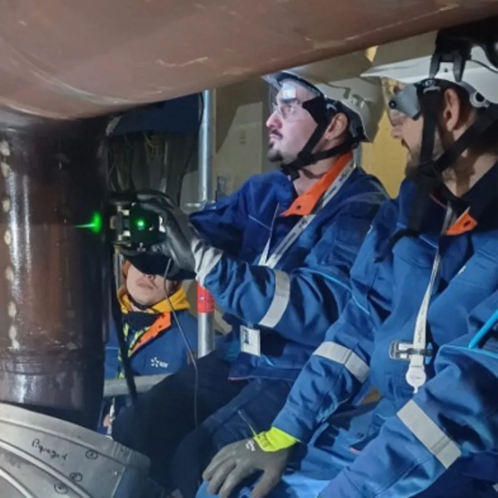
In a nuclear power plant, piping wall thickness is more than a maintenance parameter. It is core data for structural integrity, regulatory compliance and long-term operation (LTO) decisions. If thinning in primary and secondary piping, elbows and valves is not measured accurately and on time, the result can be an unplanned outage, a costly repair or a safety risk.
This guide explains why and how piping wall thickness is measured in nuclear plants, the limits of classic manual ultrasonic readings, and how encoded phased array (PAUT) corrosion mapping overcomes them, using Ekoscan METIS, developed to the requirements of French nuclear operator EDF, as an example.

Why piping wall thickness is critical in nuclear plants
Plant piping runs at high temperature, pressure and flow velocity. Especially in the secondary circuit carrying water and steam, flow-accelerated corrosion (FAC) and erosion thin the pipe wall over the years. Thinning usually concentrates where flow changes direction or velocity: elbows, tees, reducers, valves and downstream of orifices. Plants therefore run monitoring programmes that measure the wall thickness of selected components at every outage and compare it with earlier readings.
These programmes answer three questions:
- Is the pipe above its minimum allowable wall thickness today?
- How fast is it thinning?
- Is the remaining life sufficient until the next inspection or replacement?
Reliable answers need repeatable, comparable measurements.
The classic method: manual spot UT and its limits
Traditionally, the pipe surface is marked with a grid; at each point the operator takes a reading with a single-element probe and an ultrasonic thickness gauge, often writing the result on a form by hand. The method is simple and cheap, but at nuclear scale it has serious limits:
- Poor traceability: paper records and manual transfer do not make data audit-ready.
- Low repeatability: the result depends on where and how the operator places the probe.
- Transcription errors degrade data quality.
- Local thinning between grid points can be missed.
- Complex geometries (elbow intrados and extrados, tee connections) are hard to measure with standard probes.
- Long time and heavy manpower; time in radiation areas, poor ergonomics and chemical couplants raise safety risk.
The solution: encoded phased array corrosion mapping
Phased array ultrasonic testing (PAUT) uses many elements in one probe to scan a wide strip at once. When the probe is mounted on a scanner and moved with position encoders, every thickness value is stored with its position. Instead of spot values, the result is a colour C-scan thickness map of the pipe surface.
- Near-full area coverage: local thinning between grid points becomes visible.
- Comparable data: the same area is measured with the same coordinates in every campaign, so thinning rate is calculated directly.
- Digital, audit-ready records: no handwriting.
- Less time: more data in less time and less time spent in radiation areas.
How Ekoscan METIS works
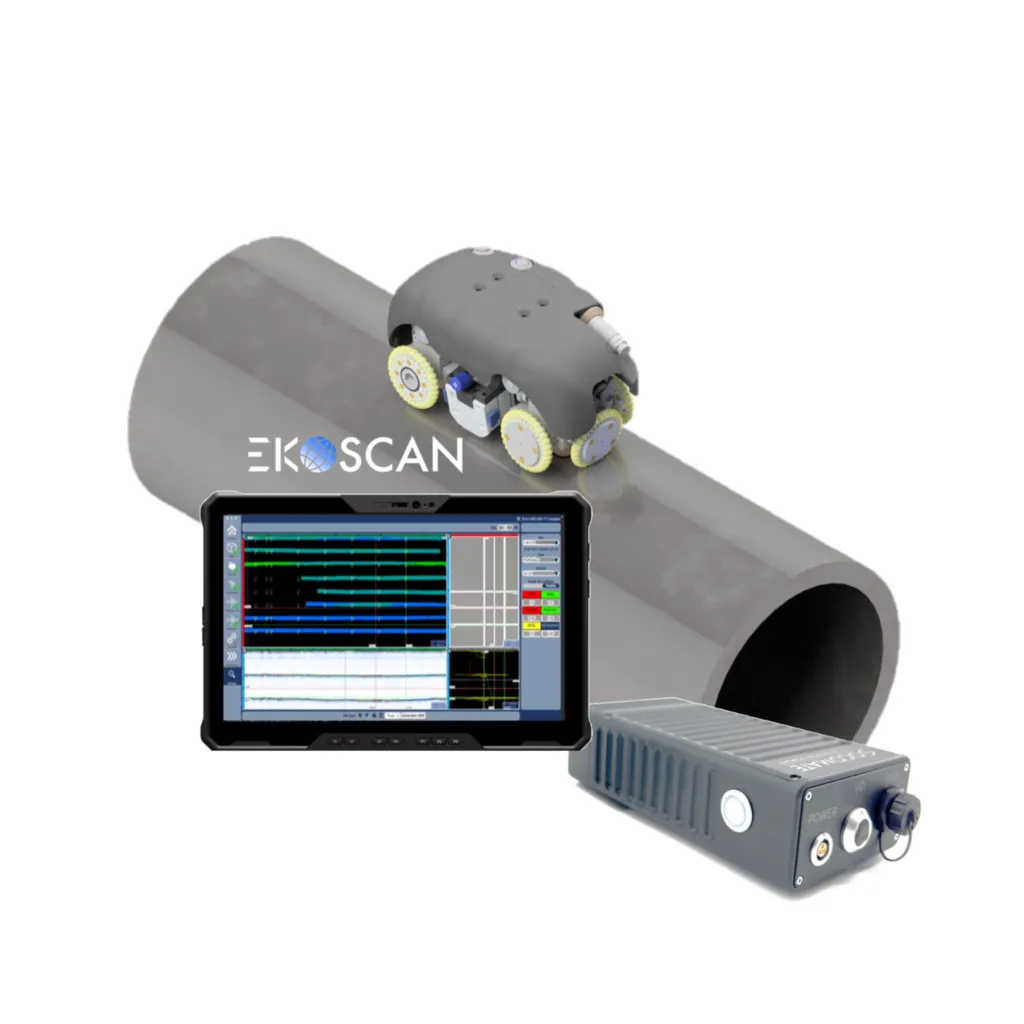
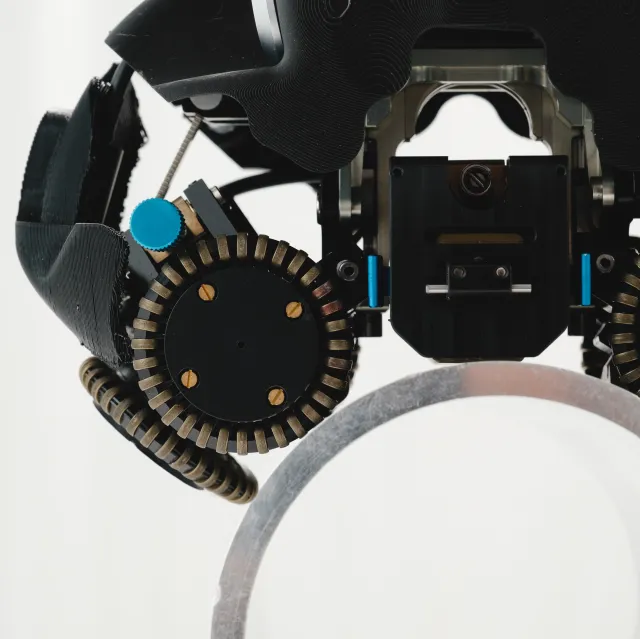
Ekoscan METIS is a compact, modular, field-deployable inspection system developed for nuclear piping wall thickness measurement. It has four core components:
- Flexible phased array probe: conforms to pipe curvature and complex geometries, keeping good contact on flat surfaces and small-diameter pipes alike.
- Dual-axis encoded acquisition: encoders on the scanner wheels record the position of each reading on two axes.
- Real-time analysis and EDF-compliant digital recording: the thickness map builds on screen during the scan; data is validated and recorded in the field.
- Guided workflow: the interface guides the operator from setup to reporting, so operators of different levels can use the system.
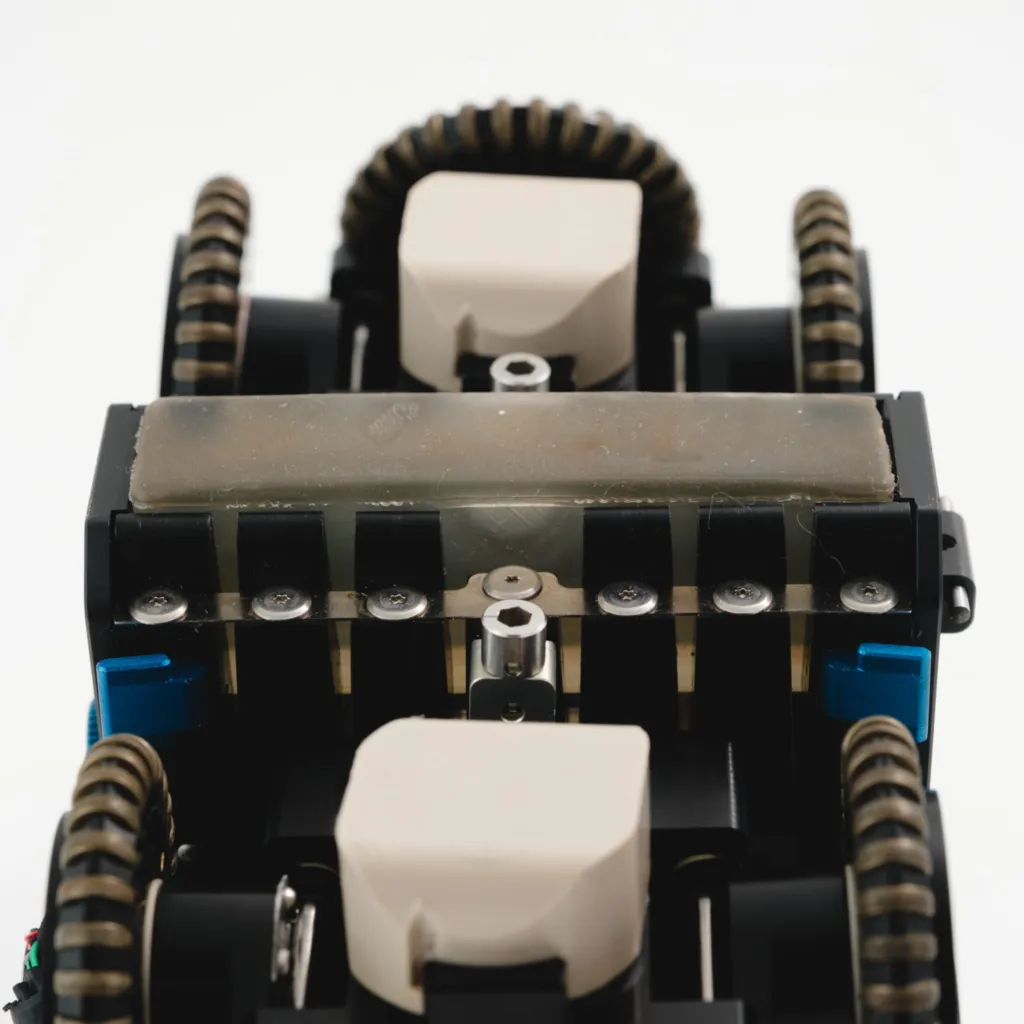
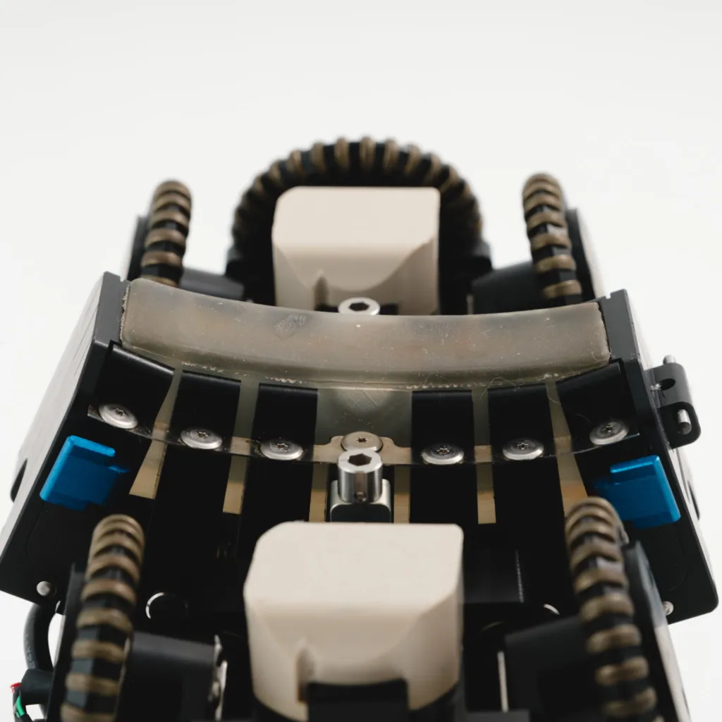
The two images above show the advantage of the flexible probe: the same probe bends from flat to follow the pipe curvature, so separate rigid probe and wedge sets are not needed for each diameter and elbow.
In the field, step by step
- Select component and zone: the elbow, tee, reducer or straight pipe from the monitoring programme.
- Quick setup: place the scanner on the pipe and enter component details in the guided workflow.
- Encoded scan: the operator moves the scanner along the pipe; the thickness map appears instantly.
- Validate in the field: coverage and data quality are checked before leaving; missing areas are rescanned at once.
- Record and compare: data is stored digitally and compared with earlier campaigns to assess thinning rate and remaining life.
Gains
| Topic | Manual spot UT | Encoded PAUT with METIS |
|---|---|---|
| Coverage | Grid points | The whole scanned area (C-scan map) |
| Records | Mostly handwritten | Digital, position-tagged, audit-ready |
| Repeatability | Operator dependent | High, with encoded position |
| Complex geometry | Difficult | Handled by the flexible probe |
| Operators | Experienced specialists | Several levels, with a guided workflow |
| Couplant and consumables | Heavy | Reduced |
Gains reported by Ekoscan include denser inspection per campaign, shorter setup and acquisition time, fewer specialist operators, repeatable data for LTO decisions, less hazardous couplant and interoperability with legacy systems.
Not only nuclear
Flow-accelerated corrosion and erosion cause the same problems in steam and feedwater lines of thermal power plants, process piping in refineries and petrochemical plants and the chemical industry. Encoded phased array corrosion mapping is replacing spot readings there too.
Choosing the right scanner
Different applications need different scanners. For thickness and corrosion mapping, METIS; for weld inspection, WELDSCAN and for girth welds REVOLVER DUAL; for nozzles, NANOSCAN NOZZLE; for automated corrosion mapping on large tanks and pipes, BANDIT; for hot surfaces, THERMALSCAN. See all options under Manual Scanners and Automated Scanners, and phased array instruments under PAUT Instruments.
Frequently asked questions
Does phased array thickness mapping replace classic UT thickness gauging?
Not entirely. Ultrasonic thickness gauges remain the tool for spot checks, quick verification and small areas. Encoded PAUT provides full-area maps and comparable data for critical components in monitoring programmes.
What is a C-scan thickness map?
A two-dimensional map that shows wall thickness at every point of the scanned surface in colour. Thinned areas stand out, and the minimum thickness and its location are read directly.
Why does a flexible probe matter?
It conforms to pipe curvature, reduces the need for separate rigid probe and wedge sets for each diameter and complex geometry, and improves contact quality.
NEXSEN and Ekoscan
NEXSEN supplies Ekoscan products in Turkey. For Ekoscan METIS we provide demonstrations, application feasibility, training and technical support. See also Ekoscan’s phased array instrument SPIKE and eddy current solutions on the brand page. To review your plant’s thickness measurement programme together, contact us.